


Hardware Repairs / 2018-10-17 08:01:57Most Amiga hardware has now more than 20 years... so, yes, it is getting wiser PS. Follow these tips at your own risks! I cannot (and won't) be responsible for any damage that you may cause!
Installing an ACA1230 or ACA1233The ACA1230 and ACA1233 are accelerators for the A1200 from Individual Computers. They are modern and clean-built accelerators, using surface mounted components. They are without mobile parts (no fans!) and therefore totally silent... They are also plug-and-play! The are actually very easy to install: just open up the trap door under the Amiga and gently slide them in, starting with the side with the "small connector" and twisting them straight to connect them tight. Then, close the trap, fire the Amiga, and enjoy!
Changing the Amiga PSU for a Modern, Standard ATX PSUThere are now lots of ATX PSU for sale for cheap in second-hand stores, which are in perfect conditions. They can be bought for less than $CA10 and used to effectively replace the old Amiga PSU with more power (watts) to support more extensions. There are a few steps to follow to use a ATX PSU:
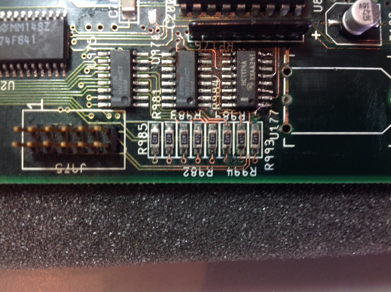
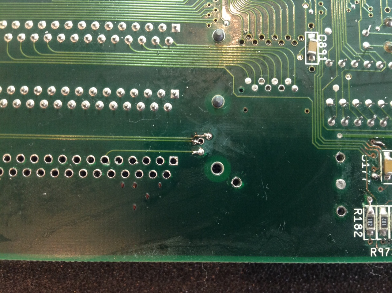
Fixing a A4000 Motherboard with Damage due to a Leaking BatteryI would not recommend trying to fix damage due to a leaking battery at home! Trust experts, like AmigaKit, even then find that difficult! In particular because the leak damaged "through holes" and connection under the memory sockets
Connecting a Arananet and ENC28J60 moduleThe Vampire is an amazing card that really give a second life to the Amigas! It can be equipped with a combo Arananet+ENC28J60 module to provide an Ethernet port and access to the Internet Arananet PinsMy Arananet came with 12 pins and two soldered wires next to the 5V and GND pins. These two wires are connected to the 5V and GND pins!
5V   oo GND
     oo
     oo INT
SI   oo S0
CS   oo SCK
3,3V oo GND
ENC28J60 Module PinsIn theory, the pins of a ENC28J60 module are:
CLK oo INT WOL oo S0 SI oo SCK CS oo REST VCC oo GND BUT, on my ENC28J60 module, the pins are as follows because there are two models of modules, with 10 or 12 pins! 5V oo GND INT oo CLK S0 oo WOL SCK oo SI RST oo CS Q3 oo GND ConnectionsHere a table showing the correspondance (hence, the connections) between the two: Thanks XRay and guibrush! | |||||||||||||||||||||||||||||||||
 but also needs some repairs. Here are some repairs and tips.
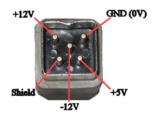

 . Here are some pictures of the step to fix the damage, courtesy of AmigaKit:


 . Usually, the Aranenet and the